System introduction
5.1 Overview of fire extinguishing agent
HFC-227ea (also known as FM200, chemical formula: CF3CHFCF3) fire extinguishing agent is a colorless, tasteless, non-corrosive, low toxicity, non-conductive, high fire extinguishing efficiency gas, clean and pollution-free, no damage to the atmospheric ozone layer (ozone consumption potential ODP is zero). Hfc-227ea gas fire extinguishing system as fire extinguishing agent is considered as an ideal product to replace halon 1211 and 1301 fire extinguishing system, which has been widely used at home and abroad.
5.1.1 Fire extinguishing mechanism
1) Chemical inhibition: HFC-227ea fire extinguishing agent can inert active free radicals in the flame and block the chain reaction during combustion.
2) Cooling: when HFC-227ea fire extinguishing agent is ejected from the nozzle, the liquid fire extinguishing agent is rapidly transformed into the gas phase, which needs to absorb a lot of heat, reducing the temperature around the flame in the protection area.
3) Asphyxia: The discharge of fire extinguishing agent in the protected area reduces the concentration of oxygen and the speed of combustion.
5.1.2 Application Scope
Hfc-227ea fire extinguishing agent can extinguish the following fires. Hfc-227ea fire extinguishing agent cannot extinguish the following fires
a) Electrical fire
b) solid surface fire
c) Liquid fire
d) Gas fire that can cut off the air source before extinguishing a) nitrocellulose, sodium nitrate and other oxidants or chemicals containing oxidants
Product fire
b) Potassium, magnesium, sodium, titanium, pick, uranium and other active metal fire
c) Fire of metal hydrides such as potassium hydride and sodium hydride
d) Fire of self-decomposing chemical substances such as hydrogen peroxide and dimethylamine
e) Deep fire of combustible solid material
5.2 Working Principles and Startup Modes of the system
5.2.1 Working principle and process
When the fire detector (temperature detector, smoke detector) detects the fire, the fire signal will be fed back to the fire alarm controller, which controls the sound and light alarm and sends out the evacuation alarm signal. At the same time, the fire alarm controller transmits the signal to the gas fire extinguishing control panel, which controls the interlocking equipment. After 30 seconds delay, it sends a start signal to the electromagnetic drive (DC24V, 1.5A). The electromagnetic drive opens the valve of the driving gas container, drives the gas to open the selection valve and the container valve of the fire extinguishing agent bottle set in sequence, and releases the fire extinguishing agent. The extinguishing agent is sprayed into the protection zone through the nozzle to achieve the purpose of extinguishing the fire. When the fire extinguishing agent flows through the pipeline, the signal feedback device operates, and the electrical signal feedbacks to the gas fire extinguishing control panel, indicating that the fire extinguishing agent has been discharged.
Figure 1 System flow chart
5.2.2 System Boot Mode
The system has three starting modes: automatic starting, manual starting and mechanical emergency starting.
1) Start automatically
When the control mode of the fire extinguishing alarm control device is set to the "automatic" position, the whole fire extinguishing system is in the automatic starting state. When the fire occurs in the protected area, the alarm control device will send out a signal, control the sound and light alarm, send out the evacuation alarm signal, and control the linkage equipment (fans, air conditioners, etc.). After a delay of 30 seconds, the fire extinguishing instruction is issued, the driving gas cylinder group is opened, the driving gas is released, the selection valve in the corresponding protection area and the fire extinguishing agent bottle group are opened, the fire extinguishing agent is released, and the fire extinguishing is implemented.
2) Start manually
In case of fire in the protected area, after being confirmed by the on-site personnel, press the manual button of the fire extinguishing alarm control device (or the start button on the "emergency start/stop" button), open the driving gas bottle group, release the driving gas, open the selection valve and fire extinguishing agent bottle group in the corresponding protected area, release the fire extinguishing agent and implement the fire extinguishing.
Note: Emergency stop operation means that when the system sends a fire alarm or the system has been manually started, and abnormal conditions (false alarm, personnel not evacuated in time, etc.) are found within the system delay time, without the need to start the system to release the fire extinguishing agent, you can press the stop button at the door of the protection area to prevent the fire extinguishing agent.
3) Mechanical emergency start
In the case of failure of automatic and manual starting, the operator should first close unnecessary openings such as linkage equipment and Windows, manually open the electromagnetic drive on the drive gas bottle group, open the drive gas bottle group, release the drive gas, open the corresponding selection valve and fire extinguishing agent bottle group, release the fire extinguishing agent, and extinguish the fire. If the electromagnetic drive and drive gas cylinder group cannot open the corresponding selection valve and fire extinguishing agent bottle group due to unknown reasons, the selection valve in the corresponding protection area should be opened manually first, and then the fire extinguishing agent bottle group should be opened manually to release the fire extinguishing agent and extinguish the fire.
Warning: The system must be operated by trained and skilled personnel, other personnel are not allowed to move. Mechanical emergency starting is not part of normal system starting and should only be used as a last resort in an emergency.
5.3 System Classification Components
Hfc-227ea gas fire extinguishing system is a fully submerged fire extinguishing system, which mainly consists of three parts: fire detection system (fire detector, alarm controller), fire control system (gas fire extinguishing control panel, sound and light alarm, emergency start/stop button, etc.) and gas fire extinguishing system. The gas fire extinguishing system is divided into unit independent system and combined distribution system.
Unit independent system: a HFC-227en supply source protects a single protected area or object through fixed pipe network and nozzle. There is no selection valve in the system, and one drive gas cylinder group is used to start all HFC-227ea fire extinguishing agent cylinder group.
Combined distribution system: a HFC-227en supply source protects two or more protected areas or objects through zone selection valves, fixed pipe networks and nozzles.
5.4 System Models
Description of HFC-227ea fire extinguishing equipment Model:
QMQ 4.2 / * N
Pressure mode: N stands for internal storage pressure
Fire extinguishing agent bottle group volume: 70, 90, 120, 150, 180, unit: L
Storage pressure of extinguishing agent, unit: MPa
Hfc-227ea fire extinguishing equipment
5.5 Main Parameters
Design working pressure (20℃) (MPa) 4.2
Extinguishing agent injection time (s) ≤10
System operating temperature (° C) 0 to 50
System operating voltage (V) DC24
System operating current (A) 1.5
Driving gas cylinder group filling pressure (20℃) (MPa) 6.0
Main parts of the system
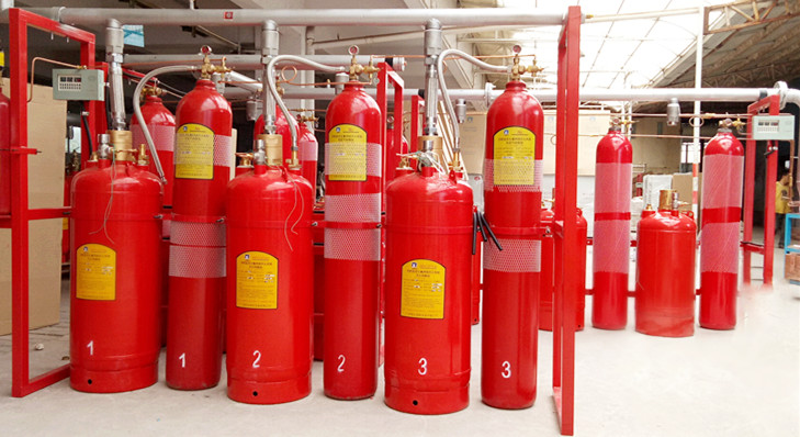
6.1 Fire extinguishing agent bottle Group
Figure 3. Fire extinguishing agent bottle group and container valve
6.1.1 Structure: It is mainly composed of container, container valve, manual device, siphon, safety discharge device, fire extinguishing agent sampling port, pressure gauge and accidental injection protection device, etc.
6.1.2 Usage Instructions
Fire extinguishing agent and pressurized nitrogen were filled according to the design requirements, and HFC-227ane fire extinguishing agent was stored in liquid form in the bottle group.
1) When starting automatically or manually, the control air flow from the driving gas cylinder group enters the manual device and drives the needle to open the container valve and release the fire extinguishing agent.
2) Mechanical emergency start: When the pneumatic mode cannot open the container valve, pull out the manual safety pin (marked with the nameplate), and press the manual pressure cap of the manual device to open the container valve. However, in the combined distribution system, the selection valve in the corresponding protection area should be opened before the manual pressure cap can be pressed.
3) When the pressure in the bottle group exceeds the pressure borne by the safety diaphragm, the safety diaphragm will spontaneously burst, and the extinguishing agent will be discharged through the safety hole to play a protective role.
4) The valve is equipped with a pressure gauge switch, which can be locked under normal circumstances to ensure that the pressure gauge is sealed. At regular intervals, loosen the fastening nut 1 turn to check the gas pressure in the cylinder.
5) The pressure gauge has a pressure gauge valve, so it can be unloaded in transit and replaced on site.
Warning:
(1) When the container valve is disconnected from the system pipeline, the misinjection protection device (commonly known as "protective cap") must be installed on the outlet of the container valve. Failure to install the protective cap will cause the cylinder to move violently when accidentally started. Violation of this warning may result in death, personal injury or property damage.
(2) When disassembling/replacing the pressure gauge, ensure that the buckle nut is locked and do not rotate with the pressure gauge. To avoid gas leakage and joint loose fly out, injury. Violation of this warning may result in death, personal injury or property damage.
(3) Do not pull out the manual safety pin and press the manual button unless it is an emergency operation. Before delivery, the auxiliary safety pin must be pulled out, otherwise the bottle set cannot be started.
6.1.3 Filling Method of fire extinguishing agent
When filling, unscrew the pressure gauge of the bottle group, loosen the buckle nut for 2 turns, connect it to the pressure gauge mounting seat using the special filling equipment connector, and fill it from the pressure gauge interface. Hfc-227ethane fire extinguishing agent is pressurized by special filling equipment to make it be introduced into the fire extinguishing agent bottle group. Then the same method is used to slowly pressurize the bottle group. The pressurizing medium is nitrogen (nitrogen purity meets the requirements specified in GB/T 8979). When the pressure of the bottle group reaches the pressure specified in GB25972-2010, the pressurization is stopped, the filling equipment is removed, the pressure gauge is installed, and the female screw is tightened.
Note: In view of the high degree of automation of the system, the system links, sealing performance requirements are strict. The filling of fire extinguishing agent shall be completed by the unit with professional qualification or the Company. It is strictly prohibited for the unit without qualification to fill it by itself.
6.1.4 Basic Parameters
Specification and model volume
(L) Nominal diameter of container valve (mm) height of bottle group
H (mm) Outside diameter of bottle group D (mm)
QMP70/4.270 DN321280 Φ 325
QMP90/4.290 DN321515 Φ 325
QMP120/4.2120 DN401345 Φ 415
QMP150/4.2150 DN401390 Φ 465
QMP180/4.2180 DN501380 Φ 520
Maximum working pressure (50℃) : 5.3MPa; Filling pressure (20℃) : 4.2MPa; Maximum filling density ≤950Kg/mm³
6.2 Drive gas cylinder group
Figure 4 Drive gas cylinder group
6.2.1 Structure: It is mainly composed of container, driving gas container valve, electromagnetic driver (with indicator light) and pressure gauge, and is filled with nitrogen.
6.2.2 Usage Instructions
1) When starting automatically or manually, in case of fire alarm, the fire alarm controller will output the start signal (DC24V, 1.5A), and the electromagnet in the electromagnetic drive on the corresponding valve of the container valve of the driving gas cylinder group will pull in, the puncture needle will break the diaphragm, open the valve of the driving gas container, and release the high-pressure nitrogen in the driving gas cylinder group. The corresponding selection valve and the container valve of fire extinguishing agent bottle group are opened successively through the gas control line to release HFC-227ea fire extinguishing agent.
2) When the mechanical emergency starts, first pull out the upper limit device of the electromagnetic drive and manually tap (press) the manual button to open the drive gas bottle set. If the driving gas cylinder group is under no pressure or due to fault maintenance, manually open the selection valve and fire extinguishing agent cylinder group corresponding to the fire protection area in sequence to release the fire extinguishing agent.
3) The valve is equipped with a pressure gauge switch, which can be locked under normal circumstances to ensure that the pressure gauge is sealed. At regular intervals, loosen the fastening nut 1 turn to check the gas pressure in the cylinder. After checking, the pressure gauge switch should be locked.
4) The pressure gauge has a pressure gauge switch, so it can be unloaded in transit and replaced on site.
5) When checking the electromagnetic drive, you need to insert the safety pin to prevent misoperation. Pull out the safety pin when the check is finished.
Warning:
(1) When disassembling/replacing the pressure gauge, ensure that the buckle nut is locked and do not rotate with the pressure gauge. To avoid gas leakage and joint loose fly out, injury. Violation of this warning may result in death, personal injury or property damage.
(2) Do not pull out the limiting device and press the manual button unless it is an emergency. Otherwise, the system will start incorrectly.
6.2.3 Basic Parameters
specification
Filling pressure (MPa) Working pressure (MPa) Volume (L) Total height H (mm) Working voltage V) Working current (A)
QQP8/6.0 6.0 8 720 DC 24 ≤1.5
6.3 Liquid check valve
Figure 5 Liquid check valve
6.3.1 Structure: mainly composed of valve body and spool.
6.3.2 Usage Instructions
1) The liquid check valve is used to prevent the backflow of fire extinguishing agent from the collecting pipe to the bottle group. The upper end is connected to the one-way valve seat of the collector pipe, and the lower end is connected to the connecting pipe, and should be installed vertically (note: the arrow direction is upward).
2) When the fire extinguishing agent is released, the fire extinguishing agent flows through the connecting pipe, pushes up the liquid check valve spool, and gathers in the flow collecting pipe.
6.3.3 Basic Parameters
Specification Model Diameter φmm Outer diameter D mm connection thread M1 connection thread M2 Length L mm
QYD32/5.33266 M48 x 2 M48 x 2 108
QYD40/5.34080 M60 x 2 M60 x 2 123
QYD50/5.35094 M68×2 M72×2 132
6.4 Gas check valve
Figure 6 Gas check valve
6.4.1 Structure: mainly composed of valve body, spool, etc.
6.4.2 Usage Instructions: It is used in the combined distribution system and installed in the gas control pipe to control the one-way flow of driving gas and the number of opening cylinders.
Note: The installation direction of the gas check valve must be consistent with the engineering design, otherwise the system will fail.
6.4.3 Basic Parameters
Operating pressure (MPa) Opening pressure (MPa) Nominal diameter (mm) Both ends of the connection thread
QD6/17.217.2 0.16 or less M10x1. 5
φ8 expansion
6.5 Connecting Pipes
Figure 7 Connecting the pipe
6.5.1 Structure: It is mainly composed of stainless steel bellows and stainless steel wire sleeves with connecting nuts at both ends.
6.5.2 Instructions for use: Connect it between the container valve (outlet) and the liquid check valve (inlet) of the fire extinguishing agent bottle group. Both ends are sealed with O-ring. As flexible parts, easy to install, and play a pressure buffer role.
6.5.3 Basic Parameters
Nominal diameter (mm) Working pressure (MPa) Connection thread M Total length L(mm)
QRG32/5.3325.3 M45 x 2400
QRG40/5.3405.3 M45 x 2500
QRG50/5.3505.3 M64 x 2600
6.6 Safety Valve
Figure 8 Safety valve
6.6.1 Structure: mainly composed of valve body, safety bursting diaphragm assembly and safety valve cap.
6.6.2 Instructions for use: The safety valve is usually installed on one side of the collector tube. When the pressure in the collector tube is greater than the allowed value, the safety bursting diaphragm will burst and release the pressure to protect the system.
Note: The relief port of the safety valve should not face the operating surface, channel, etc.
6.6.3 Basic Parameters
Diaphragm bursting pressure (MPa) connection thread
QAX7.57.2